Grid-Forming vs. Grid-Following Inverters: The Technical Blueprint for Modern Grid Resilience
Executive Summary: As global energy grids transition from synchronous generators to high-penetration inverter-based resources (IBRs), the distinction between Grid-Following and Grid-Forming architectures becomes critical. This guide analyzes the control logic, stability impacts, and commercial ROI of these technologies for system integrators and utility-scale developers.
Table of Contents
- What is the Core Difference Between Grid-Forming and Grid-Following Inverters?
- Grid-Following (GFL) Architecture: The Current Source Standard
- Grid-Forming (GFM) Technology: Enabling Virtual Synchronous Machines (VSM)
- Technical Comparison Table: GFL vs. GFM
- Overcoming Weak Grid Instability and Low SCR Challenges
- Moneypro Energy Manufacturing: Why Component Selection Matters
- B2B Application Guide: Residential to Utility-Scale
- FAQ: Grid-Forming Implementation
- Industry References
Key Takeaways for System Integrators
- Grid-Following (GFL) inverters act as current sources and require a stable external voltage/frequency reference provided by the grid.
- Grid-Forming (GFM) inverters function as voltage sources, capable of establishing grid parameters independently, essential for black starts and microgrids.
- Stability: GFL inverters struggle in “weak grids” with a Short Circuit Ratio (SCR) below 3.0, whereas GFM inverters thrive by providing synthetic inertia.
- Moneypro Advantage: Our GFM-ready PCS units utilize Infineon IGBTs and 48-hour high-temperature aging to ensure 98.8% efficiency and 20-year design life.
What is the Core Difference Between Grid-Forming and Grid-Following Inverters?
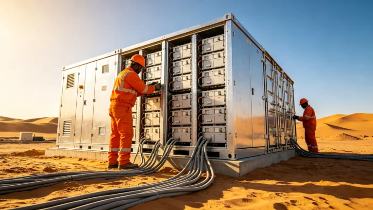
A Battery Energy Storage System (BESS) is an integrated electrochemical system that captures energy from various sources (solar, grid, wind) and stores it in battery modules for subsequent discharge to manage peak loads, provide backup power, or stabilize the grid.
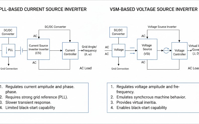
In traditional power systems dominated by synchronous generators (like coal or gas turbines), the massive rotating mass provides natural inertia that stabilizes frequency. As we move toward 100% renewable penetration, we lose this physical inertia. Grid-following inverters, like those traditionally produced by Sungrow or Huawei, rely on a Phase-Locked Loop (PLL) to synchronize with the grid. If the grid frequency fluctuates too rapidly or the voltage collapses, the PLL can lose its lock, leading to mass tripping of renewable assets.
Conversely, Grid-Forming technology, pioneered in specialized microgrid applications by manufacturers like SMA and now integrated into Moneypro Energy’s utility-scale Power Conversion Systems (PCS), uses Virtual Synchronous Machine (VSM) algorithms. These GFM inverters do not “follow” the grid; they “be” the grid. They provide instantaneous response to load changes by adjusting their voltage angle, effectively emulating the behavior of a physical turbine.
Grid-Following (GFL) Architecture: The Current Source Standard
Grid-following inverters operate as a controlled current source, where the output current is regulated to track the grid voltage phase using a Phase-Locked Loop (PLL).
GFL architecture is the industry standard for the vast majority of grid-tied PV systems and Battery Energy Storage Systems (BESS). The control logic is centered around Maximum Power Point Tracking (MPPT) and power factor regulation. In this setup, the inverter assumes the grid is an “infinite bus” with a stable voltage and frequency. It measures the grid’s phase angle and injects a sinusoidal current that is precisely aligned (or shifted for reactive power) with that angle.
Technically, GFL inverters utilize an inner current control loop with high bandwidth. This allows for fast response to irradiation changes but makes them sensitive to grid impedance. When connected to a weak grid—characterized by high impedance and low Short Circuit Ratio (SCR)—the PLL can become unstable. Moneypro Energy’s GFL string inverters mitigate this by employing advanced resonance suppression algorithms and multi-resonant controllers, ensuring THDi remains below 3% even under distorted grid conditions. However, GFL inverters cannot perform a “black start” (energizing a dead grid) because they have no reference to synchronize with.
The Rise of Grid-Forming (GFM) Technology: Enabling Virtual Synchronous Machines (VSM)
Grid-forming inverters function as a controlled voltage source that provides synthetic inertia and primary frequency control, making them indispensable for high-RE (Renewable Energy) penetration.
GFM technology is the “holy grail” for grid stability. Instead of a PLL, GFM inverters use droop control or Virtual Synchronous Machine (VSM) models. A VSM-based inverter mimics the swing equation of a physical generator. When the load increases, the inverter’s internal frequency drops slightly (emulating inertia), allowing the system to naturally share the load without waiting for a signal from a central controller. This inherent response is much faster than traditional AGC (Automatic Generation Control).
At Moneypro Energy, our GFM PCS units are engineered for utility-scale resilience. We incorporate high-speed DSPs (Digital Signal Processors) that compute the VSM control loop at 20kHz. This allows for instantaneous voltage support during transients. Furthermore, GFM inverters are capable of “Black Start,” meaning they can energize a microgrid or a transmission line after a total blackout. This capability is a significant value-add for Commercial Building Energy Storage and Data Center Energy Storage, where downtime is not an option.
Technical Comparison Table: GFL vs. GFM Inverter Specs
| Feature | Grid-Following (GFL) | Grid-Forming (GFM) |
|---|---|---|
| Control Objective | P-Q Control (Current Source) | V-f Control (Voltage Source) |
| Grid Reference | Required (PLL) | Self-Generated (Internal Osc.) |
| Inertia Provision | None (or slow synthetic) | Inherent Virtual Inertia |
| Weak Grid Stability | Unstable (SCR < 3.0) | Highly Stable (SCR > 1.0) |
| Black Start | No | Yes |
| Hardware Requirements | Standard IGBTs/LCL Filters | Over-dimensioned IGBTs (for fault current) |
| Typical Application | Standard Grid-tied PV/ESS | Microgrids, Weak Grids, Islanding |
Overcoming Weak Grid Instability and Low SCR Challenges
Grid-forming inverters maintain stability in weak grids with a Short Circuit Ratio (SCR) as low as 1.0, where traditional grid-following inverters would trigger protection relays.
In remote areas or at the end of long transmission lines—common for Solar Farm Energy Storage—the grid is “weak.” The SCR represents the strength of the grid relative to the inverter’s capacity. In these environments, the voltage is highly sensitive to current injections. A GFL inverter’s PLL might struggle to maintain synchronization, leading to oscillations or “hunting.” This instability was a major factor in historical grid events involving large wind and solar farms in Australia and California.
GFM inverters solve this by acting as a voltage anchor. Because they don’t rely on a PLL to define their firing pulses, they aren’t confused by voltage distortions or phase jumps. In fact, GFM inverters strengthen the grid for other GFL inverters nearby. By installing a Moneypro Grid-Forming PCS at a solar farm, developers can effectively “stiffen” the grid, allowing for higher total capacity without expensive transmission upgrades. This provides a direct ROI by reducing the need for synchronous condensers.
Moneypro Energy Manufacturing: Why Component Selection Matters
The reliability of GFM inverters is determined by their thermal management and the quality of their power electronics, specifically the IGBT modules and DC-link capacitors.
Grid-forming operation is harder on hardware. Because the inverter must act as a voltage source, it must be able to provide high reactive current during faults to help clear breakers. This requires significant “headroom” in the power electronics. While consumer-grade inverters might use lower-cost MOSFETs, Moneypro Energy uses Infineon PrimePACK™ IGBTs and Nippon Chemi-Con aluminum electrolytic capacitors rated for 105°C.
Our manufacturing process includes a rigorous 48-hour high-temperature aging test at 50°C under full load. This ensures that every PCS leaving our factory can handle the 110% continuous overload and 150% short-term fault current required for true grid-forming service. Our PCS architecture is modular, allowing for N+1 redundancy in Factory Energy Storage applications, significantly reducing O&M costs over a 20-year lifecycle. We achieve a peak efficiency of 98.8%, minimizing heat waste and maximizing the ROI of every lithium-ion cycle.
B2B Application Guide: When to Choose GFL vs. GFM?
Choosing the right architecture depends on the grid’s characteristics and the project’s reliability requirements. Below are our recommendations for various sectors:
- Residential Solar Storage: Standard GFL with simple islanding (backup) is usually sufficient. Moneypro’s Hybrid Inverters provide seamless <10ms switching. View Residential Battery Energy Storage System
- Commercial Building Energy Storage: GFM is recommended if the facility requires a high degree of UPS-like reliability or has large inductive loads (elevators, HVAC) that require high starting currents. View Commercial Energy Storage System
- Factory Energy Storage: GFM is critical for facilities with sensitive CNC machinery or internal microgrids that must remain operational during utility outages. View Industrial Energy Storage System
- Grid Stabilization & Remote Power Systems: GFM is mandatory. These projects rely on GFM to set the frequency and voltage for the entire system, often paired with diesel generators or wind turbines.
For more detailed application notes, visit our specialized solutions pages:
- Residential Solar Storage
- Commercial Building Energy Storage
- Factory Energy Storage
- Grid Stabilization
- Remote Power Systems
FAQ: Grid-Forming Implementation
Can I mix Grid-Forming and Grid-Following inverters in the same system?
Yes, and this is the most common configuration for large-scale BESS. Typically, a small percentage (10-20%) of the total capacity is GFM-capable to provide the voltage reference and inertia, while the remaining GFL inverters provide bulk power. This optimizes costs while maintaining stability.
What certifications are required for GFM inverters?
In the US, UL 1741 SB and IEEE 1547-2018 are the benchmarks. In Europe, EN 50549-1 and G99 (UK) are essential. Moneypro Energy products are fully certified for global markets, including TUV and CE compliance.
Does GFM increase the cost of the PCS?
Generally, yes. GFM requires more advanced control software and hardware over-dimensioning to handle fault currents. However, the ROI comes from avoiding synchronous condensers and enabling higher renewable penetration on-site.
Ready to Upgrade Your Grid Stability?
Project RFQ: Submit your utility-scale or C&I project requirements for a comprehensive technical proposal and ROI analysis. Request RFQ Today →