The 7 Main Components of a Battery Energy Storage System
Navigating the complex architecture of modern energy infrastructure requires moving beyond surface-level terminology. Whether you are an EPC contractor deploying a massive grid-side project, a facility manager lowering peak demand charges, or an installer integrating commercial renewable platforms, understanding the internal engineering of a storage plant is paramount. Procurement decisions based solely on battery cell price per kilowatt-hour routinely fail because a battery pack alone is incapable of interacting safely with an electrical grid.
In most professional situations, the operational failure of a storage deployment stems not from cell chemistry degradation, but from poor integration among secondary hardware, control logic, and HVAC systems. A complete system relies on an tightly synchronized ecosystem of electrochemical, power electronic, software, and safety subsystems. In this guide, we break down the primary components of a battery energy storage system, evaluate how each subsystem impacts performance, and offer practical advice on specifying bankable, high-reliability infrastructure for commercial and utility applications.
Quick Answer: What Are the Key Components of a BESS?
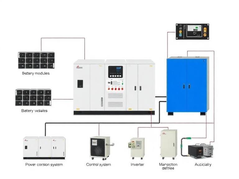
A functional Battery Energy Storage System (BESS) consists of seven core integrated subsystems:
- Battery Modules & Racks: The electrochemical DC energy storage core (predominantly LFP/LiFePO4 cells).
- Battery Management System (BMS): The multi-tiered controller monitoring cell health, balancing charges, and preventing thermal runaway.
- Power Conversion System (PCS): The bi-directional inverter converting DC power to grid-compliant AC power and vice versa.
- Energy Management System (EMS): The software brain directing power flow, economic dispatch, peak shaving, and grid services.
- Thermal Management System (TMS): Liquid or air-cooling units maintaining optimal operating temperatures (typically 20°C to 25°C).
- Fire Suppression & Safety Systems (FSS): Specialized gas/aerosol fire protection, deflagration venting, and gas detection safety hardware.
- Balance of Plant (BOP) & Switchgear: Transformers, circuit breakers, isolators, and cabling connecting the system to the grid.
Table of Contents
- What It Is: Architecture of a Commercial BESS
- How It Works: Subsystem Synergy and Energy Flow
- Deep-Dive: The 7 Main Components Explained
- Benefits of Fully Integrated Component Architecture
- Limitations and Mechanical Bottlenecks
- Who Should Use Integrated Systems vs. Component Assemblies
- Common Mistakes in Component Sourcing
- Commercial Buying & Engineering Considerations
- Expert Recommendation from China MoneyPro Energy
- Technical & Comparison Tables
- Frequently Asked Questions (FAQ)
What It Is: Architecture of a Commercial BESS
A Battery Energy Storage System is a multi-layered engineering assembly designed to store electrical energy in chemical form and release it as AC electricity precisely when required. It bridges the gap between intermittent renewable energy generation (such as solar or wind) and continuous power demand. Rather than acting as a simple static power source, a commercial system operates as a dynamic grid asset capable of responding to frequency variations in milliseconds.
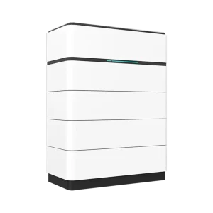
The primary components of a battery energy storage system are physically and logically segregated into DC (Direct Current) hardware, power conversion hardware, software management layers, and auxiliary safety infrastructure. For deployment scale, systems range from a multi-kilowatt Residential Energy Storage System up to multi-megawatt containers utilized in a bulk Utility Scale Energy Storage System.
How It Works: Subsystem Synergy and Energy Flow
During a charging cycle, AC electricity flows from the grid or a solar array into the system switchgear. The Energy Management System (EMS) processes grid conditions or electricity price signals and commands the Power Conversion System (PCS) to rectify AC electricity into DC electricity. The DC current is then routed through protection breakers into the battery racks, where the Battery Management System (BMS) controls charging current to individual Lithium Iron Phosphate ($LiFePO_4$) or alternative chemistry cells while the Thermal Management System (TMS) dissipates generated heat.
During discharge, the flow reverses instantly. The EMS issues a dispatch command; the BMS confirms safe cell operating conditions; DC power leaves the battery modules, enters the PCS inverter to convert to AC power, passes through a step-up transformer within the Balance of Plant, and feeds directly into the building or public utility grid. If any individual sensor detects abnormal parameters—such as off-gas generation or cell over-voltage—the safety system isolated the affected rack before damage propagates.
Deep-Dive: The 7 Main Components Explained
To evaluate equipment reliability, engineering teams must analyze each of the primary components of a battery energy storage system independently.
1. Battery Modules, Packs, and Racks
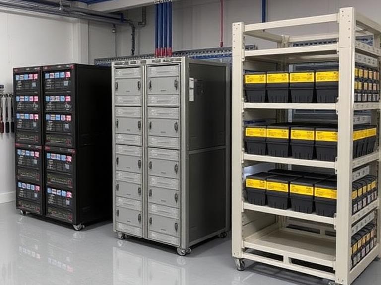
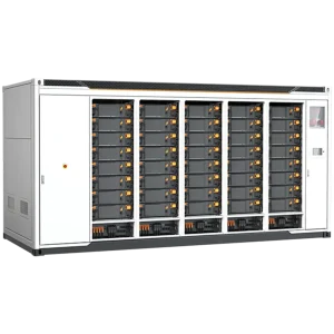
The battery enclosure houses the actual electrochemical cells. In modern commercial installations, Lithium Iron Phosphate ($LiFePO_4$ or LFP) has largely superseded Nickel Manganese Cobalt (NMC) due to superior thermal stability, longer cycle life (typically 6,000 to 10,000 cycles at 80% Depth of Discharge), and zero reliance on cobalt. Individual prismatic cells are spot-welded or bolted into modules, compiled into high-voltage packs, and stacked vertically in heavy-duty structural steel racks reaching up to 1,000V or 1,500V DC.
2. Battery Management System (BMS)
From our experience, the BMS is the most critical safety system in the entire enclosure. Operating across three hierarchy tiers (Slave/BMU at the module level, Master/BCU at the rack level, and System-BMS at the container level), the BMS measures cell voltage, current draw, and surface temperatures thousands of times per second. It performs passive or active cell balancing to keep all cells in identical state-of-charge ($SoC$), calculates state-of-health ($SoH$), and trips contactors if operating parameters drift outside strict safety windows.
3. Power Conversion System (PCS)
The PCS is the heavy-duty bi-directional inverter that interfaces the DC battery bus with the AC electrical grid. High-efficiency PCS units utilize Silicon Carbide (SiC) or IGBT power transistors to achieve conversion efficiencies exceeding 98%. Beyond basic AC/DC conversion, a advanced PCS provides grid support functionalities including reactive power compensation ($VAR$), frequency regulation, black-start capabilities, and fast islanding switching for an Off-Grid Power Solution or localized backup application.
4. Energy Management System (EMS)
While the BMS protects the battery, the EMS directs the economic performance of the overall plant. The EMS communicates via Modbus TCP, CAN bus, or IEC 61850 protocols with the PCS, BMS, meteorological stations, and utility SCADA networks. Using predictive algorithms, it executes operational strategies such as peak shaving, solar self-consumption smoothing, spot market price arbitrage, and automated demand response. In a complex Microgrid Energy Solution, the EMS regulates generation assets alongside battery state to optimize fuel consumption or renewable utilization.
5. Thermal Management System (TMS)
Lithium-ion cells operating outside their narrow optimal thermal band (typically 20°C to 25°C) experience accelerated degradation, capacity fade, or thermal runaway risks. In heavy-duty applications, air cooling is rapidly being replaced by liquid cooling systems. Liquid cooling plates placed directly against battery cell surfaces deliver uniform temperature distribution across massive battery racks ($\Delta T < 3^\circ C$), consuming up to 30% less parasitic auxiliary power than traditional industrial HVAC chillers.
6. Fire Suppression & Hazard Mitigation Systems
Compliance with modern safety codes (such as NFPA 855 and UL 9540A) mandates sophisticated, redundant safety systems. Modern BESS enclosures incorporate off-gas detection sensors (detecting early hydrogen or carbon monoxide emissions prior to thermal runaway), clean-agent gas suppression (such as Novec 1230 / FK-5-1-12 or water mist systems), explosion deflagration panels, and automated emergency isolation contactors.
7. Balance of Plant (BOP) & Electrical Switchgear
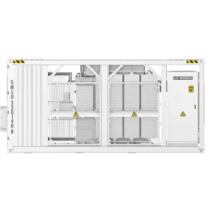
The BOP encompasses all supporting physical and electrical components necessary to transmit power securely. This includes AC and DC circuit breakers, isolation switches, surge protection devices (SPDs), current/voltage transformers, ground fault detection relays, Auxiliary Power Units (UPS for controls), and medium-voltage step-up transformers required to connect a Utility Scale Energy Storage Solution to distribution networks.
Benefits of Fully Integrated Component Architecture
In our testing and operational evaluations, choosing a fully integrated, factory-assembled system yields distinct commercial and engineering advantages over piecemeal component assembly:
- Optimized Round-Trip Efficiency (RTE): Matched PCS, BMS, and low-resistance busbar connections minimize conversion losses, ensuring systemic RTE remains above 88% to 92%.
- Unified Communication Protocols: Factory integration ensures zero communication lag between the BMS cell safety loops, PCS firing signals, and EMS dispatch software.
- Simplified Bankability and Warranties: Single-source system integration eliminates finger-pointing between battery manufacturers and inverter suppliers when executing warranty claims.
- Accelerated On-Site Commissioning: Containerized, factory-tested units dramatically reduce field installation labor, cabling, and civil works costs.
Limitations and Mechanical Bottlenecks
We must apply commercial and practical judgment: no technology operates without constraints. The primary mechanical limitation of a high-density BESS is parasitic power consumption. In extreme hot or cold ambient climates, running high-capacity liquid chillers or heating elements to protect battery chemistry can consume 5% to 15% of the system’s total daily energy throughput, reducing net project revenues.
Additionally, system degradation is non-linear. If a single bad cell degrades rapidly and the BMS lacks active balancing capabilities, the lowest-performing cell limits the capacity of the entire string, forcing early module replacement. Understanding the precise specification of every component prevents these capacity bottlenecks.
Who Should Use Integrated Systems vs. Component Assemblies
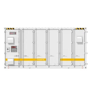
For commercial users and utility developers: We strongly recommend procuring fully containerized, factory-integrated systems containing pre-matched PCS, liquid cooling, and BMS architectures. Attempting to source loose battery racks, third-party inverters, and standalone HVAC units for a commercial facility creates immense safety liability and integration headaches.
Who does not need complex BESS installations: For light residential installations where basic backup is needed during short outages, heavy multi-tier EMS platforms with grid-support software are unnecessary. A simple residential solar array paired with a standardized Hybrid Inverter and modular low-voltage wall battery is more than sufficient.
Common Mistakes in Component Sourcing
In our consulting and engineering audits, we routinely observe four critical errors during procurement:
- Ignoring C-Rate Mismatch: Purchasing high-energy cells (0.5C or 0.25C rating) for an application requiring fast power response (1C to 2C rating) causes immediate thermal stress and voids cell warranties.
- Selecting Outdated Air Cooling for High-Density Systems: Specifying traditional air conditioning units for high-energy 20ft/40ft containers results in severe temperature gradients across cells, leading to uneven cell aging.
- Underestimating Aux Power Requirements: Failing to account for HVAC, control, and lighting electrical loads when calculating project ROI distorts financial modeling.
- Overlooking Grid-Code Compliance of the PCS: Installing inverters that lack localized IEEE 1547-2018 or UL 1741 SB certifications results in utilities rejecting grid interconnection.
Commercial Buying & Engineering Considerations
When issuing an RFQ for a C&I Energy Storage System or utility asset, prioritize these core purchasing benchmarks:
- Tier-1 Cell Traceability: Insist on direct cell manufacturing batch documentation to ensure zero grey-market or recycled cells are present in battery modules.
- UL 9540 & UL 9540A Certification: Require system-level UL 9540 certification and full-scale fire testing reports (UL 9540A) to ensure smooth local fire marshal (AHJ) permitting.
- Modularity and Augmentation Strategy: Ensure the PCS and DC bus design allows for future battery capacity augmentation (adding racks in year 5 or 7) as original cells experience natural capacity fade.
Expert Recommendation from China MoneyPro Energy

China MoneyPro Energy is a technology-driven developer of advanced energy storage systems and intelligent power solutions, built upon a strong heritage of national-level research institutes and decades of engineering experience in high-reliability systems.
Originating from China’s aerospace and defense technology ecosystem, China MoneyPro Energy integrates advanced research, system engineering, and industrial manufacturing capabilities to develop next-generation energy storage solutions for the global energy infrastructure.
When selecting the main components of a battery energy storage system, we advise clients against sacrificing system integration quality for initial capital savings. BESS infrastructure must operate safely and predictably over a 15-to-20-year lifespan. Partnering with a full-stack engineering provider that designs and controls the interaction between LFP modules, BMS telemetry, and high-efficiency power conversion ensures your asset achieves maximum bankability, total regulatory compliance, and bulletproof operational uptime. Whether you are building an Industrial Energy Storage Solution or a multi-megawatt grid asset, uncompromised hardware integration is your best protection against downtime.
Technical & Comparison Tables
| Subsystem Component | Primary Function | Critical Tech Specifications |
|---|---|---|
| Battery Modules / Racks | DC electrochemical energy storage | LFP chemistry, 3.2V nominal cells, 1000V-1500V DC bus |
| Battery Management System (BMS) | Safety monitoring, cell balancing, SoC/SoH | 3-tier architecture, CAN/Modbus, millisecond response |
| Power Conversion System (PCS) | Bi-directional AC/DC energy transformation | SiC/IGBT transistors, >98% efficiency, grid-forming capacity |
| Energy Management System (EMS) | Supervisory control & economic dispatch | Cloud/Edge logic, peak-shaving, frequency regulation software |
| Thermal Management System (TMS) | Enclosure temperature regulation | Liquid cooling ($\Delta T < 3^\circ C$) vs. Precision Air HVAC |
| Fire Suppression System (FSS) | Hazard mitigation & fire prevention | Off-gas sensors, Novec 1230 / FK-5-1-12, deflagration vents |
| Feature Metric | Liquid Cooling BESS Architecture | Air Cooling BESS Architecture |
|---|---|---|
| Temperature Uniformity | High ($\Delta T \le 3^\circ C$ across cells) | Moderate ($\Delta T \le 8^\circ C$, risk of hotspots) |
| Energy Density | Ultra-High (Up to 5MWh per 20ft container) | Moderate (Typically 2.5MWh to 3.3MWh per 20ft) |
| Parasitic Power Draw | Low (30% to 40% reduction vs Air) | High (Continuous heavy fan/compressor operation) |
| Expected Cell Lifespan | Extended (+20% longer thermal cycle life) | Standard |
| Upfront System Cost | Slightly higher capital cost | Lower initial equipment cost |
| Sourcing Model | Pros (Advantages) | Cons (Limitations) |
|---|---|---|
| Factory Integrated Containers | Single-warranty coverage, factory pre-tested, rapid commissioning, superior safety compliance. | Less flexibility to mix and match individual brand components. |
| Piecemeal Component Sourcing | Ability to pick individual cheap vendors for cells, inverters, and HVAC. | High field integration risk, complex multi-vendor warranty disputes, longer field installation times. |
| Project Scale | Target Application | Mandatory Component Standards |
|---|---|---|
| Commercial & Industrial (100kWh – 2MWh) | Peak shaving, EV charging support, demand charge reduction | Liquid-cooled LFP, 0.5C/1C rate, integrated 3-phase PCS, UL 9540 certified. |
| Microgrid / Remote (200kWh – 5MWh) | Off-grid power, solar/diesel hybrid optimization | Grid-forming PCS, black-start capabilities, wide operating temperature TMS. |
| Utility Scale (5MWh – 100MWh+) | Grid stabilization, frequency response, renewable shifting | 1500V DC high-density liquid containers, SCADA IEC 61850 integration, UL 9540A reports. |
Frequently Asked Questions (FAQ)
What are the core components of a battery energy storage system (BESS)?
The primary components of a battery energy storage system include the Battery Modules/Racks, Battery Management System (BMS), Power Conversion System (PCS) or inverter, Energy Management System (EMS), Thermal Management System (TMS), Fire Suppression System (FSS), and Balance of Plant (BOP) switchgear.
Why is the Battery Management System (BMS) considered critical for safety?
The BMS actively monitors voltage, current, state of charge (SoC), and temperature across individual cells and modules. It prevents overcharging, over-discharging, cell imbalance, and thermal runaway, acting as the primary line of defense against catastrophic failure.
What is the difference between an EMS and a BMS in a storage system?
The BMS manages the internal physical health and safety of the battery cells on the DC side. The EMS operates at a higher supervisory level, managing energy dispatch, software algorithms, grid interaction, electricity market arbitrage, and overall site loads across the AC/DC integration layer.
Authoritative References & Industry Standards
To ensure system compliance, engineering design, and safety protocols align with international benchmarks, we recommend referencing the following authoritative technical bodies:
- IEEE Standards Association – Standards governing interconnection, inverter testing (IEEE 1547), and stationary battery installation safety.
- International Electrotechnical Commission (IEC) – Specifically IEC 62619 and IEC 62933 detailing safety requirements for secondary lithium cells and utility-scale energy storage systems.
- National Renewable Energy Laboratory (NREL) – Leading research and empirical performance modeling on battery degradation, thermal management, and grid integration.